


As-built surveyDrawings of the building as it actually is.
Original drawings describe a building as someone intended to build it. After the second fit-out they describe something that no longer exists. An as-built survey replaces that guess with measurement. It is the drawing half of an existing conditions survey.
What you get
Every drawing type comes from the same capture, so the plan, the elevation and the ceiling plan agree with each other. That sounds obvious until you have worked with a set assembled from three site visits by three different people.
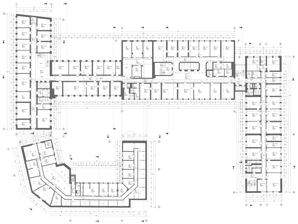
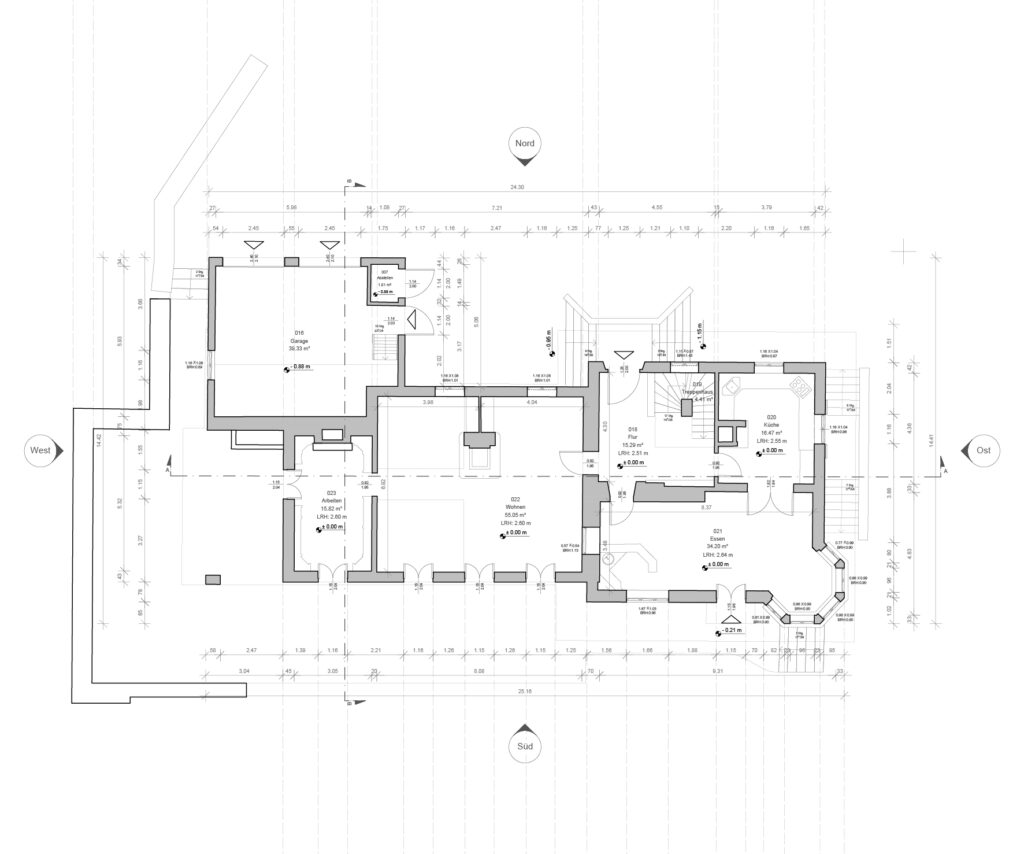
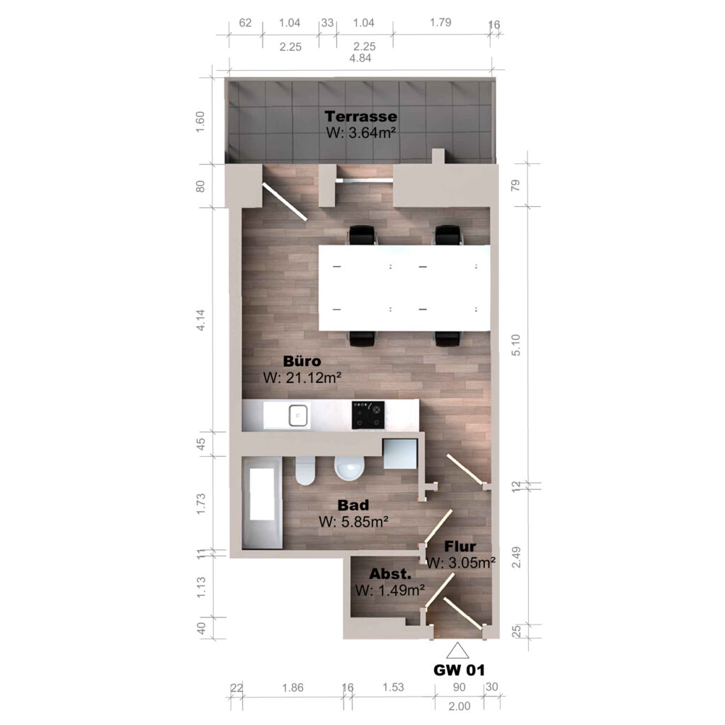
- Floor plans — walls, openings, columns, fixed furniture, level changes, dimensioned.
- Exterior and interior elevations — true-scale, straight-on views of each face.
- Sections — cut where you need them, with floor and wall build-ups as measured.
- Reflected ceiling plans — grid, fixtures, diffusers, sprinklers, soffits, height changes.
- Site and roof plans where the scope reaches outside.
Drawn to your standard, not ours
Layer naming, line weights, title blocks, dimension styles, text heights — we produce to the standard your office already uses. It saves your team the redraw, and it means the file drops into your existing project instead of starting a reformatting job.
If you do not have a written standard, we work to ours and hand it over as a document, so the next consultant on the project has something to follow.
The point cloud comes with it
You receive the registered scan in E57 or RCP alongside the drawings. Any dimension that comes up later gets checked against measurement rather than against memory — and nobody has to go back to site to answer a question that could be answered from the desk.
How a project runs
-
Scope
We agree which drawing types you need, to what accuracy, and in which file standard — before anyone mobilizes. This is the conversation that decides the price.
-
Capture
Terrestrial scanning for detail, mobile mapping for large floor areas, drone for roofs and facades. Method chosen per area, not per project.
-
Register and verify
Scans are tied into one coordinate system and checked against each other. Nothing gets drawn from an unverified cloud.
-
Draft and review
Drawings are produced to your standard, then reviewed by someone who did not produce them.
-
Handover
DWG, DXF and the registered point cloud. One round of revisions included.
Where it pays for itself
Renovation and adaptive reuse · tenant fit-out · due diligence before acquisition · permit sets for buildings with no usable record · coordination on sites where trades keep discovering that the wall is not where the drawing says. Where the project runs in Revit rather than in 2D, the same capture feeds a scan to BIM model.
The common thread is always the same: somebody is about to commit money based on a document nobody has verified. Older stock is where the gap is widest — on pre-war buildings we routinely find floor-to-floor dimensions several inches off the record set. That is enough to stop a new stair or shaft from landing.
Drawing types, scales and formats
All of these are cut from one registered point cloud, which is why they agree with each other. Scale is what decides how much detail a sheet can carry legibly, so it is agreed at scope rather than at delivery.
| Drawing | What it carries | Usual scale | Format |
|---|---|---|---|
| Floor plan | Walls, openings, columns, fixed furniture, level changes, dimensioned. | 1/8″ or 1/4″ to the foot | .dwg, .dxf, .pdf |
| Exterior elevation | Each facade straight on, at true scale, with openings and datum heights. | 1/8″ to the foot | .dwg, .dxf, .pdf |
| Interior elevation | One wall of one room: casework, tile, fixture and switch heights. | 1/4″ or 1/2″ to the foot | .dwg, .dxf |
| Section | Floor build-ups, structural depth, ceiling voids, storey-to-storey heights. | 1/8″ or 1/4″ to the foot | .dwg, .dxf |
| Reflected ceiling plan | Grid, fixtures, diffusers, sprinklers, soffits, height changes. | 1/8″ to the foot | .dwg, .dxf |
| Roof and site plan | Plant, drainage, parapet and level information where scope reaches outside. | 1/16″ or 1/8″ to the foot | .dwg, .dxf |
Layer naming, line weights, title blocks and dimension styles follow your office template. If there is no written standard, we deliver ours as a document so the next consultant has something to follow. What each drawing type answers is set out in the knowledge center.
What a set contains, by building type
Tenant fit-out and office
Plans, one section per core, and a reflected ceiling plan for every floor in scope. The ceiling plan is the sheet that gets used most on a fit-out, because lighting, sprinklers and diffusers all have to move together and none of them are where the old drawing says. Column grids come from measurement rather than from the record set, which is where most base-building drawings are quietly wrong.
Healthcare and laboratory
Everything above, plus interior elevations in wet rooms and imaging suites, and sections through service corridors. Equipment clearances and door swings decide whether a room works at all, so both are dimensioned rather than drawn to look right. Where the retrofit touches services, the ceiling void is opened and documented rather than represented as a blank space.
Industrial and manufacturing
Plans at coarse scale, sections where equipment meets structure, and elevations only where something is being built against. The valuable drawing here is rarely the plan: it is the section that shows crane clearance, slab thickness or the gap between a duct and a new mezzanine. Racking and plant are drawn as installed when they are staying and omitted when they are not.
Historic and landmarked
Elevations carry the work, and they are drawn from the cloud rather than straightened. Out-of-plumb walls, settled openings and irregular bays are documented as measured, because a drawing that quietly squares them up is worse than no drawing. Profiles and moldings are captured at full resolution where they will be replicated, and detail sheets are cut straight out of the point cloud.
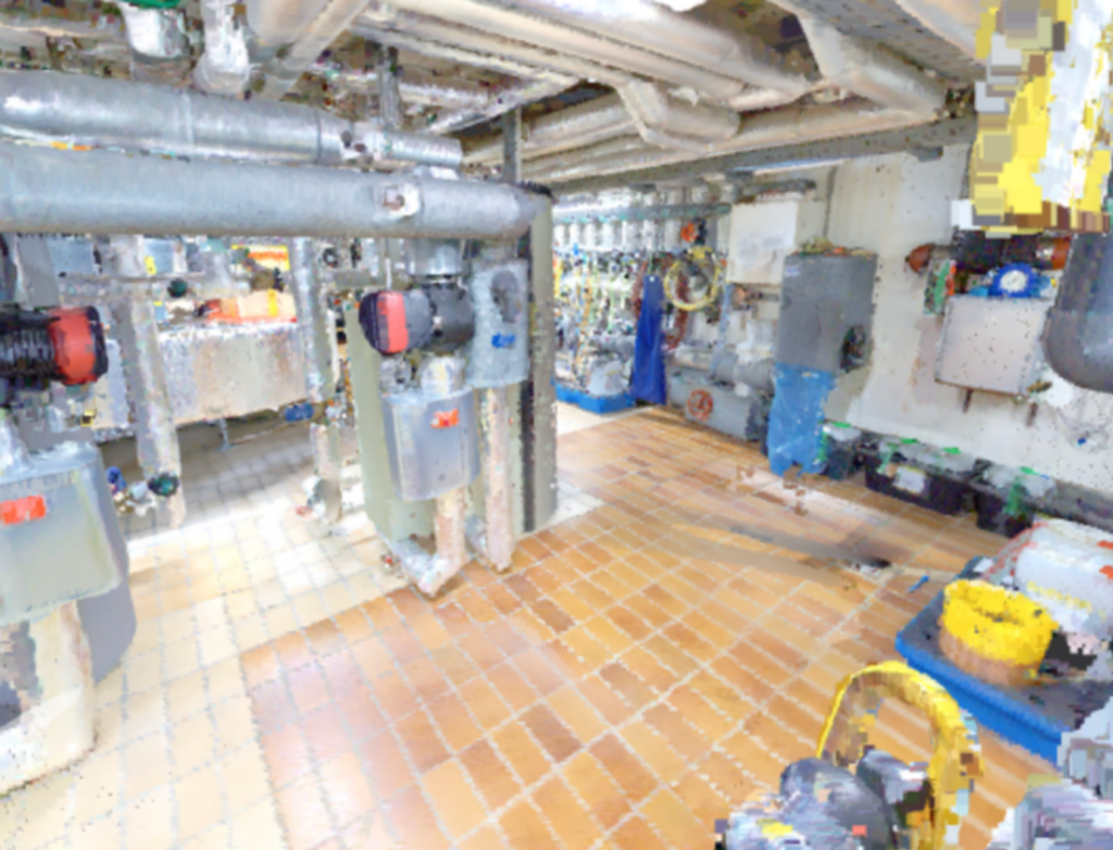
Where an as-built set goes wrong
- Squaring up what is not square. Drafting software wants right angles. A pre-war building does not have them. We draw the measurement, and where a wall runs out by two inches over thirty feet, the drawing says so.
- Structure behind finishes. A scanner sees the surface, not the column inside the drywall. Concealed structure is either inferred and labeled as inferred, or opened up and measured. It is never drawn as if it had been seen.
- Floor levels treated as one number. Slabs dish, screeds vary, and a single finished floor level across a plate is a fiction. Where it matters we deliver level points or a deviation map rather than one figure.
- Above-ceiling left out silently. If the void was not opened, the ceiling plan shows the underside and nothing else. That is stated on the sheet, not left for the mechanical engineer to discover.
- Someone else’s conventions. A set drawn in unfamiliar shorthand costs your team time to read, which defeats the point of buying it. We ask for your legend sheet before drafting starts.
When drawings are not what you need
- If the project will be coordinated in three dimensions, the drawings are a by-product of scan to BIM and ordering them separately costs more than ordering both.
- If the question is operational rather than architectural, room and asset records under facility management data answer it better than a drawing set does.
- If nobody will build against it and the need is to look at the space, a virtual tour is a fraction of the price.
- If the building has already been documented and the question is what changed, say so at scope. Comparing a new capture against an existing set is a smaller job than a full survey.
Frequently asked questions
What is an as-built survey?
A measured record of a building as it stands today, turned into drawings. It differs from a design drawing in one important way: it documents what is there, not what was intended.
How is it different from a land survey?
A land survey establishes boundaries, topography and position on the site. An as-built survey documents the building itself. Projects often need both, and they are usually done by different specialists.
How long does it take?
Capture runs 32,000–65,000 sq ft per day in offices and up to 107,000 sq ft in open industrial space. Drafting time depends on how many drawing types you need, not on how big the building is.
Do you work from our existing drawings?
Yes, and we like to have them. They tell us what to expect on site, and the differences between the record set and the measurement are often what the client actually wanted to know.
What accuracy can we expect?
Terrestrial laser scanning is millimeter-accurate. Across a registered project we hold deviation under 0.4 inches in our own point cloud comparison, and we report the figure for your project rather than a brochure number. Where mobile mapping covers large floor areas, the result is dimensionally accurate rather than millimeter-accurate — and we tell you which method produced which part of the deliverable. Where the brief specifies a USIBD Level of Accuracy, we confirm which level applies to which area before mobilizing.
How do you handle above-ceiling areas?
Where the scope includes services in the ceiling void, tiles are lifted and the void is scanned directly. It adds 20–40% to the cost and is worth it on a mechanical retrofit — and wasted on a space plan. We ask which one you are doing before quoting. Rates and what moves them are on the pricing page.
What about occupied buildings?
Most of our work happens in buildings that stay in use. Scanning is quiet, needs no lighting, and people can keep working around it. Where a space has to be empty, we schedule outside business hours — which is normal rather than exceptional in dense metros, and standard practice on our New York work.
Can you match an existing drawing set?
Yes. Bring the old set and we will produce to the same conventions, so the new drawings sit alongside the old ones without a visual break. Comparing the two is frequently the most useful part of the deliverable.
What file formats do we receive?
.dwg and .dxf for drawings. .e57 or .rcp for the registered point cloud. .pdf plot sets on request. If your workflow needs something else, ask — most formats are a export setting rather than a project.
Tell us about the building
Type, rough size, and what you need to do with the data. We will come back with the method and the deliverables that fit.
Our deliverables document existing physical conditions. They are not a boundary survey, a land title survey, or an ALTA/NSPS Land Title Survey, and they are not to be used in lieu of a survey prepared by a land surveyor licensed in the state where the property is located. Where a project requires boundary, topographic, or georeferenced survey data, we work from control provided by your licensed surveyor.
Drawings and models we deliver document existing conditions. They are not construction documents. Where documents must be filed with a building department, a licensed architect or professional engineer of record reviews, adopts, and seals them.